Using switches with an Arduino – Input Pull-Up / Pull-Down
- Brainy-Bits
- Oct 24, 2020
- 3 min read
Updated: Oct 27, 2020

OVERVIEW
At some point you will have to connect and use switches to control stuff in your Arduino projects.
Here are some basics to successfully use switches and make sure they respond correctly.

Most switches are simple mechanical devices that basically make a connection between two inputs.
In this tutorial we will be using a standard tact switch.
A tact switch is a momentary mechanical switch that makes a connection when the switch is pressed.
There are two things we can detect with an Arduino:
Detect when the switch is pressed or not pressed
Detect if the switch is HIGH (5V) or LOW (Ground) in either of those 2 states
PARTS USED
Arduino NANO
Tact Switches
These are Amazon affiliate links...
They don't cost you anything and it helps me keep the lights on
if you buy something on Amazon. Thank you!
WHY DO WE NEED A RESISTOR WHEN USING A SWITCH?

You connect one of those either to Ground (LOW) or 5V (HIGH) and connect the other one to an Arduino Digital pin.

This is an example of ‘FLOATING"
When the switch is pressed it makes the connection between those two pins and connects the Arduino Digital pin to either Ground or 5V which we can detect in code and do the appropriate action.
But when the switch is not being pressed it enters a state of “Floating”.
Floating is when the Arduino Digital pin is neither High or Low and results in noise.
So to fix this we connect the tact switch pin that is connected to the Arduino Digital pin to either Ground or 5V depending on what we are trying to read when the switch is pressed.
So if we want to read LOW when the switch is pressed we would connect the 5V, which will results in the switch being “Pulled UP” when the switch is not being pressed and the Arduino would read the Digital pin HIGH without any noise.

Here the pin is Pulled UP to 5V when the switch is not being pressed…
Now we can’t just go ahead and connect that pin directly to ground or 5V since that would create a short circuit when the switch is pressed, this is why we need to use a Resistor.
The Resistor prevents the short circuit by limiting the amount of current to flow when the switch is pressed.
RESISTOR VALUE AND ARDUINO INTEGRATED PULLUP RESISTORS
In your projects you can either use external resistors or the ones available inside the Arduino.
The Arduino UNO has PullUp resistors available on each one of the Digital Pins.
These are activated inside your code and have a value between 20k and 50k (average of around 34k).
Notice that the Arduino UNO only has PullUp resistors and no PullDown resistors, which mean that using the Arduino resistors only enables you to make the state of the switch when it’s not pressed to HIGH (PullUp), which is not a big problem since most of the time you want to read HIGH when not pressed and LOW when the switch is pressed.
To my knowledge only the Arduino ZERO has both PullUp and PullDown resistors.
If you project need to read LOW when the switch is not pressed then you will need to use external resistors, and a value between 20k and 50k will provide the same results as if using the Arduino resistors.
CONNECTIONS DIAGRAMS
In this tutorial we will look at 4 different connections scenarios:
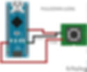
Demonstrate the Floating state

Using a resistor to PullUp

Using the Arduino integrated resistor to PullUp

Using a Resistor to PullDown

THE CODE
To visualize what happens when I press the tact switch, I’m using a MAX7219 LED Matrix.
The Matrix will display a ZERO or a FIVE (Ground or 5V) when the switch is pressed.
If the scenario is a PULLUP then the matrix will display a FIVE when the switch is not pressed and a ZERO when it is pressed.
If the scenario is a PULLDOWN then it will do the opposite.
You can find links to the library used to control the LED Matrix at the bottom of this page.
As always don’t forget to watch the tutorial video for more information.
#include <MD_Parola.h>
#include <MD_MAX72xx.h>
#include <SPI.h>

#define HARDWARE_TYPE MD_MAX72XX::ICSTATION_HW
/*  PAROLA_HW,    ///< Use the Parola style hardware modules.
    GENERIC_HW,   ///< Use 'generic' style hardware modules commonly available.
    ICSTATION_HW, ///< Use ICStation style hardware module.
    FC16_HW       ///< Use FC-16 style hardware module.
*/

#define MAX_DEVICES 1
#define CLK_PIN   13
#define DATA_PIN  11
#define CS_PIN    10

int switchpin=5;

// Hardware SPI connection
MD_Parola P = MD_Parola(HARDWARE_TYPE, CS_PIN, MAX_DEVICES);


void setup(void)
{
  P.begin();
  P.setTextAlignment(PA_CENTER);

  pinMode(switchpin, INPUT_PULLUP);
  // this will use the Arduino PullUp resistors

  // pinMode(switchpin, INPUT); this needs external resistor to work
}

void loop(void)
{
    if (digitalRead(switchpin) == LOW) P.print(0);
    else P.print(5);
  }
TUTORIAL VIDEO
DOWNLOAD
Copy and Paste the above code/sketch in your Arduino IDE software.
Download the Parola library here:

