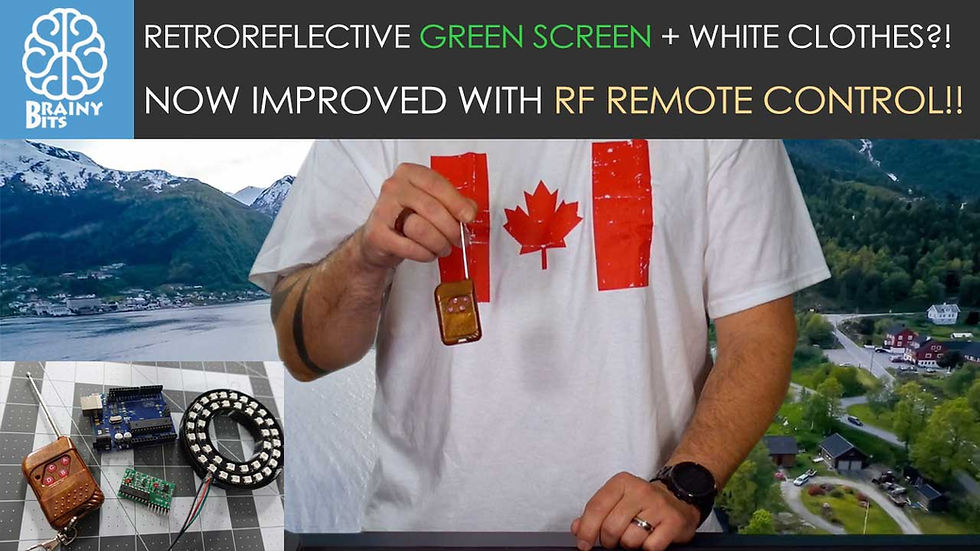
RetroReflective Green Screen Testing Update! Now with RF Remote Control!
- Brainy-Bits

- Oct 24, 2020
- 5 min read
Updated: Oct 28, 2020
OVERVIEW
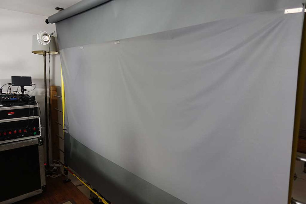
This is an update on the previous tutorial – DIY RetroReflective Green Screen – were I built a Green screen that doesn’t require any lighting and is perfect for smaller spaces.
After the tutorial appeared on YouTube I got an interresting question regarding if this would work with a subject wearing ‘White’ clothes?
The assumption is that the Green LED used to light the RetroReflective screen would turn the white clothes green and would make the keying in post harder if not impossible.
Well let’s try it out to find out!
Also while I was at it, I added a simple RF remote control to switch the colors and brightness of the LED’s to make adjustments easier to do without having to modify the Arduino code every time.
You can find the new connections and updated Arduino code below.
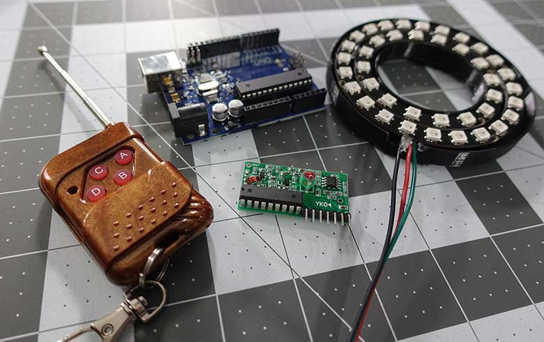
PARTS USED
Arduino UNO
WS2812 LED RING
315MHZ Remote and Receiver
These are Amazon affiliate links...
They don't cost you anything and it helps me keep the lights on
if you buy something on Amazon. Thank you!
Retroreflective Material
ADDING REMOTE CONTROL CAPABILITIES
At first when I wanted to use the RetroReflective Green Screen for one of my videos, I had to plug in the USB cable to power the Arduino UNO and right away it would light up the ring of LED’s green.
It would do this at a preset intensity that I set in the code and I didn’t have any control of this or the color.
If I wanted to change something I had to edit the Arduino code and upload the code again to see the results.
So I thought why not use a simple RF remote to control the brightness and the colour on the fly.
These RF remote are very simple to use and don’t require any coding at all.
When you press a button on the remote, the receiver which is connected to the Arduino UNO, will put the corresponding pin HIGH and the Arduino will detect this and do an action.
CONNECTIONS
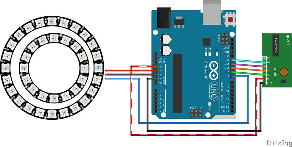
The connections for the LED Ring are the same as the previous tutorial:
The 5V and GND of the UNO is connected to the outer LED ring 5V and GND *Don’t forget that the 5V and GND on the LED ring is inverted*
Then pin 8 of the UNO is connected to the D1 pin of the LED ring
*Again inverted so it’s the D0 pin*
The inner ring has the 5V and GND of the outer ring connected together and the D0 of the outer ring is connected to the D1 of the inner ring.
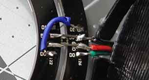
You can check my connections here:
Black wire = GND, the Red wire = 5V and the Green wire = D1 or Pin 8 of the UNO:
To connect the RF Receiver you just have to connect the pins that represent the Remote control buttons (A-D = D0-D3)
I used the 3.3V from the Arduino UNO to power the receiver module since the 5V is already used for the LED ring, and that seems to work fine.
Also connected the GND to the available GND pin of the Arduino UNO.
THE CODE
We are using the FastLED library to light up the LED ring but this time instead of hard coding the Color and Brightness we check to see if a button is pressed on the RF Remote Control and then set those according to which button was pressed.
In this case these action are:
Button A = Brightness UP Button B = Brightness DOWN
Button C = Cycle colors (Green, Blue, Red)
Button D = Turn LED’s ON and OFF (by setting the colour to Black and back to Previous color)
To see it in action don’t forget to check out the tutorial video below.
/* RF Remote Controlled RetroReflective Green Screen
 * Using WS2812 LED Ring

Created by Yvan / https://Brainy-Bits.com

This code is in the public domain...
You can: copy it, use it, modify it, share it or just plain ignore it!
Thx!

*/

#include "FastLED.h"

// How many leds are connected?
#define NUM_LEDS 40

// LED Ring digital IN connected to Arduino pin
#define DATA_PIN 8

// Define the array of leds
CRGB leds[NUM_LEDS];

// Variable used to hold color value
int current_color = 0;  // 0-green, 1-blue, 2-red 3-OFF
int old_color;  // Used to store previous color value

int current_brightness = 75;  // Startup brightness

// Which button was clicked on the RF remote?
int change_detected = 0;  // 0-no, 1-Button A or B, 2- Button C, 3- Button D

void setup() {
  FastLED.addLeds<NEOPIXEL,DATA_PIN>(leds, NUM_LEDS);
  FastLED.clear();

  // Light up LED Ring Green at startup
  for(int led = 0; led < NUM_LEDS; led++) {
    leds[led] = CRGB::Green;
  }
  FastLED.setBrightness(current_brightness);
  FastLED.show();
}

void loop() {

  if (digitalRead(9) == HIGH) {  // Button A pressed
   if (current_brightness < 200) {
    current_brightness++;
   }
   delay(5);
   change_detected=1;
  }


  if (digitalRead(10) == HIGH) {  // Button B pressed
   if (current_brightness > 0) {
    current_brightness--;
   }
   delay(5);
   change_detected=1;
  }

  while (digitalRead(11) == HIGH) {  // Button C pressed
   switch (current_color) {

    case 0:
      current_color=1;  // change color to Blue
      change_detected=2;
      delay(200);
      break;

    case 1:
      current_color=2;  // change color to Red
      change_detected=2;
      delay(200);
      break;

    case 2:
      current_color=0; // change color to Green
      change_detected=2;
      delay(200);
      break;
   }
  }

  if (digitalRead(12) == HIGH) {  // Button D pressed
   if (current_color == 3) {
    current_color=old_color;
    delay(200);
    change_detected=2;
   } else {
       old_color=current_color;
       current_color=3;
       delay(200);
       change_detected=2;
     }
  }


// Check which flag was turned on

  if (change_detected==1) {
    FastLED.setBrightness(current_brightness);
    FastLED.show();
    change_detected=0;
  }


  if (change_detected==2) {
    switch (current_color) {

      case 0:
        // Change led color to Green
        for(int led = 0; led < NUM_LEDS; led++) {
          leds[led] = CRGB::Green;
        }
        FastLED.show();
        change_detected=0;
        break;

      case 1:
        // Change led color to Blue
        for(int led = 0; led < NUM_LEDS; led++) {
          leds[led] = CRGB::Blue;
        }
        FastLED.show();
        change_detected=0;
        break;

      case 2:
        // Change led color Red
        for(int led = 0; led < NUM_LEDS; led++) {
          leds[led] = CRGB::Red;
        }
        FastLED.show();
        change_detected=0;
        break;

      case 3:
        // Change led color Black
        for(int led = 0; led < NUM_LEDS; led++) {
          leds[led] = CRGB::Black;
        }
        FastLED.show();
        change_detected=0;
        break;
    }
  }

}
THE RESULTS

After testing, it seems that even when wearing “White Clothes” the RetroReflective Green Screen still works perfectly.
This might be due to the fact that the light emitted from the LED’s fall off pretty quickly and only the RetroReflective material can reflect it at that distance (about 6 feet) and bounce it back to the camera.
So unless you’re wearing very reflective clothing you shouldn’t have any problems using this type of Green Screen.
All in all I’m very happy with the results of this project and will use this from now on when making my videos on YouTube.
Hope you enjoyed this project and hope to see you at the next one!
TUTORIAL VIDEO
DOWNLOAD
Copy and Paste the above code/sketch in your Arduino IDE software.
Donwload the FastLed library here:
You can find some 3D parts for the Camera LED ring on Thingiverse here


Great update on your DIY retroreflective green screen project—especially loved the RF remote integration and the real-world test with white clothing under green LEDs! Lighting and screen clarity matter hugely in post-production and ideal for display calibration, clean light setups, and testing visuals before a shoot. Go to WhiteScreen to prep your screen environment for flawless keying and editing.