Make a simple Arduino Game Scoreboard with 7-segment Displays
- Brainy-Bits

- Oct 24, 2020
- 4 min read
Updated: Oct 28, 2020

OVERVIEW
I’ve used and done tutorials in the past using 7 segment displays modules.
These modules are great and easy to use since they have all the parts needed onboard.
But sometimes for a project you might need to create your own so that it fits in a case or you need to space them in a particular way, that a premade module won’t fit or even exist.
Most of the 7 segment modules use the MAX7219 led display driver IC.
One MAX7219 can control up to 64 individual leds or eight 7 Segment displays.
In this tutorial we will see how to connect two 2 digits 7 Segment display and control them with an Arduino UNO using the MAX7219.
PARTS USED
Arduino UNO
2 Digits 7 Segment Display
MAX7219 IC
These are Amazon affiliate links...
They don't cost you anything and it helps me keep the lights on
if you buy something on Amazon. Thank you!
7 SEGMENT DISPLAY INTRODUCTION

So what is a 7 segment display?
A 7 segment display is basicaly just a couple of regular LEDs behind a stencil.
Each led lights up a particular segment and by lighting a specific combination of LEDs you can represent a number or some letters.
Most 7 segment display have 8 LEDs, one for each segment and another one used for the DP (decimal point).
That’s why one MAX7219 IC can control up to eight 7 segment displays, 8×8=64 individuals LEDS.
So to connect one digit directly to an Arduino you would need 8 digital pins.
That is why you want to use a LED driver like the MAX7219 that enables you to control up to 8 digits using only 3 pins.
Most 7 Segment display are common Cathode, which mean that each LED GND pins (Cathode) are connected together and the VCC+ pins (Anode) are not.
Just like a regular LED, if you reverse the polarity it will not light up.
Here’s a diagram of the 2 digit 7 Segment display we are using in this tutorial:

As you can see pin 1-5 and pin 6, 9 and 10 are connected to a specific segment.
Pin 7 and 8 (D1 and D2) are the common Cathode for each digit.
So by grounding D1 or D2 you select which digit you want to lit up a specific segment.
Of course like any LED you need to use a resistor to limit the amount of current drawn by the LED. But since we will be using the MAX7219 we will only need one resistor.
MAX7219 INTRODUCTION
Although the MAX7219 is not the only LED driver available it’s probably the easiest to use and can control many LEDs using only one chip.
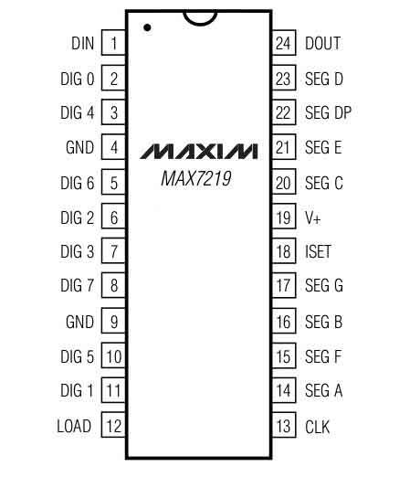
The connections are clearly identified, all you have to do is connect them to the correct pins on the 7 segment display.
You then have 3 pins to connect to the Arduino.
In addition you will need a resistor to limit the current drawn by the LEDs of the 7 segment.
Last you might want to connect some capacitors to filter out the noise from the power supply, but this is optional since I’ve built many of these without using them and never had a problem, but this is from the realm of “This is good practice”.
If you look closely you can see the pins DIG 0 through DIG 7, these are the selectors for which digit you want to select.
In our tutorial we will be using 4 of them since we have four digits.
To have a better idea on how everything is connected check out the diagram below which shows all the connections including the 10K resistor and the noise filtering capacitors.
CONNECTIONS

In this tutorial we have two 2 digits 7 segment, and two switches.
Each switch control one of the 7 segment to increase the value displayed when clicked.
You start by connecting the corresponding pins from the MAX7219 to the first 7 Segment, this includes D0 and D1 pin, then you connect the pins from the first 7 Segment to the second 7 Segment, but this time you connect the D2 and D3 pins from the MAX7219.
Since this tutorial has many connections, look at the diagram closely to see were everything is connected.
Don’t forget to put the 10K resistor between the MAX7219 “ISET” pin and the 5V power to prevent overcurrent.
THE CODE
We are using the “LedControl” library to communicate with the MAX7219 from the Arduino.
This library can be used with LED matrix or with 7 Segment displays.
In this tutorial when we click a switch, the corresponding display will increase by one, kinda like a scoreboard.
As alway check out the tutorial video to get more information.
/* Arduino 7 Segment scoreboard
 * Using the MAX7219CNG LED Driver

Created by Yvan / https://Brainy-Bits.com

This code is in the public domain...

You can: copy it, use it, modify it, share it or just plain ignore it!
Thx!

*/

#include "LedControl.h"  // Library used for communcation with 7 segment

LedControl lc=LedControl(12,11,10,1);  //  (DIN, CLK, LOAD, number of Max7219 chips)

// Variable to hold current scores
int displayone=0;
int displaytwo=0;

// Variables to split whole number into single digits
int rightdigit;
int leftdigit;

// Switches pin connection to Arduino UNO
#define switchone 2
#define switchtwo 3


void setup() {
  pinMode(switchone,INPUT_PULLUP);
  pinMode(switchtwo,INPUT_PULLUP);

  lc.shutdown(0,false);  // Wake up MAX7219

  lc.setIntensity(0,7);  // Set brightness to medium

  lc.clearDisplay(0);  // Clear all displays connected to MAX7219 chip #

// Put zeros on both displays at startup

  lc.setDigit(0,0,0,false);  // (Max7219 chip #, Digit, value, DP on or off)
  lc.setDigit(0,1,0,false);

  lc.setDigit(0,2,0,false);
  lc.setDigit(0,3,0,false);

}


void loop() {

  // If switch 1 is clicked
  if (!digitalRead(switchone)) {

    displayone++;  // Increase score by 1

    // convert whole number to single digits
    rightdigit=displayone%10;
    leftdigit=displayone%100/10;

    // Display extracted digits on the display
    lc.setDigit(0,0,leftdigit,false);
    lc.setDigit(0,1,rightdigit,false);


    // Wait until switch is released to continue
    while (!digitalRead(switchone)) {
    }
    delay(5);  // Small delay to debounce the switch
  }

    if (!digitalRead(switchtwo)) {

    displaytwo++;

    rightdigit=displaytwo%10;
    leftdigit=displaytwo%100/10;

    lc.setDigit(0,2,leftdigit,false);
    lc.setDigit(0,3,rightdigit,false);

    while (!digitalRead(switchtwo)) {
    }
    delay(5);
  }
}
TUTORIAL VIDEO
DOWNLOAD
Copy and Paste the above code/sketch in your Arduino IDE software.
Donwload the LedControl library here:


Just want to point out, the link for the 7 segment displays now goes to the CL3621AH, NOT the 5621BH which you use in your video. The pinout is completely different. (common pins are 1 and 5 on the new/updated model) I made the mistake of not checking the datasheet first and burned up 2 of the 5 in the pack -_-
EDIT: Upon further inspection, I dont think the CL3621AH is what is used in the project. That is a common anode display, which is not compatible with the 7219. I assume you just used a picture of one for the project guide. The amazon link does in fact take you to a common cathode display. The pinout of…