Best code to use with a KY-040 Rotary Encoder? Let’s find out!
- Brainy-Bits

- Oct 24, 2020
- 5 min read
Updated: Oct 28, 2020

OVERVIEW
We have used Rotary Encoders like the KY-040 before in other tutorials and it worked fine.
These rotary encoders are cheap and do work, but they have quite a bit a bouncing in them, so they are not very accurate and will sometimes turn one way when you want them to turn the other way.
That’s ok for most projects, but can we maybe make them behave better with some code?
In this tutorial we will look at a better way to code for this inaccuracy and try to get the best results possible.
PARTS USED
MAX7219 Matrix Module
Rotary Encoder Module
These are Amazon affiliate links...
They don't cost you anything and it helps me keep the lights on
if you buy something on Amazon. Thank you!
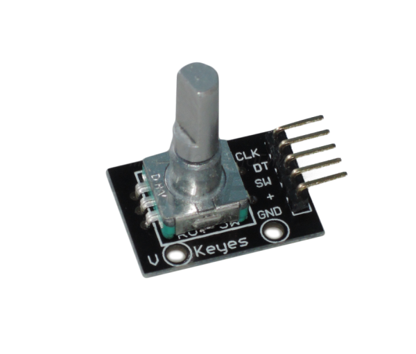
THE PINS ON THE KY-040 ROTARY ENCODER
The KY-040 has 5 pins:

CLOCK
DATA
SWITCH
VCC
and GROUND
The ones we are interested in are CLOCK and DATA.
For you see, as we rotate the shaft of the encoder, these pins will vary between HIGH or LOW depending on the direction of rotation.
So by knowing these HIGH or LOW state we can know if the signal received is going one way or the other, as well as checking if the received signal is a valid one or just the rotary encoder bouncing while we are rotating the shaft.
CONNECTIONS

Rotary Encoder connections:
Arduino Pin 2 is connected to CLOCK Pin 3 is connected to SW Pin 4 connected to DATA
LED Matrix:
Pin 10 is connected to CS Pin 11 is connected to DATA Pin 13 is connected to CLOCK
The 1st led matrix OUT pins are connected to the 2nd led matrix IN pins in parallel.
The 5V and GND of the Arduino are connected to both the Rotary Encoder and the 1st LED Matrix VCC and GND.
GETTING THE PIN STATE VALUES?
THE CODE
We will be using two Arduino codes:
First one will let us know the values of the pins (CLOCK and DATA) when we rotate the shaft CW and CCW.
The second code will be using those values to display a counter on a LED 8×8 Matrix.
So in this first Arduino sketch it reads the state of the rotary encoder pins when we rotate it and displays those values on the serial monitor.
We are using the Arduino IDE serial monitor at the highest baud rate (2,000,000bps) to make sure we can display those values as fast as possible.
When we run this code we take note of the values when we rotate the shaft clockwise and when we go counterclockwise.
Once we have those values, we will use them in the next code to check the received signal and know if it’s valid of not.
*Note: Keep in mind that this code doesn’t do much, if any debouncing (simple delay() of 5ms), so we should see some bouncing of the values when we rotate the shaft, but we can work around that and guess which values are correct.
Please check out the tutorial video to see what happens.
/* Arduino New Rotary Encoder Pin states

Created by Yvan / https://Brainy-Bits.com

This code is in the public domain...

You can: copy it, use it, modify it, share it or just plain ignore it!
Thx!

*/

volatile boolean TurnDetected;  // need volatile for Interrupts

// Rotary Encoder Module connections
const int PinCLK=2;   // Generating interrupts using CLK signal
const int PinDT=4;    // Reading DT signal

// Interrupt routine runs if CLK pin changes state
void rotarydetect ()  {
  TurnDetected = true;  // set variable to true
}

void setup ()  {
  Serial.begin(2000000);  // high rate to assure good capture
  attachInterrupt (0,rotarydetect,CHANGE); // interrupt 0 always connected to pin 2 on Arduino UNO
}

void loop ()  {

  if (TurnDetected)  { // rotary has been moved
      TurnDetected = false;  // do NOT repeat IF loop until new rotation detected
      Serial.print("CLK Pin: ");
      Serial.println(digitalRead(PinCLK));
      Serial.print("DT Pin: ");
      Serial.println(digitalRead(PinDT));
      delay(5);
  }
}
THE DEBOUNCE CODE
After running the previous Arduino sketch, here are the results:
Clockwise (Clock, Data pin): 0,1 – 1,0 – 0,1 – 1,0 – …
CounterClockwise (Clock, Data pin): 1,1 – 0,0 – 1,1 – 0,0 – …
So now we know what pin state to expect when we turn the rotary encoder CW or CCW.
In our testing we also saw the change when we went from CW to CCW or CCW to CW:
Clockwise to CounterClockwise: 0,1 –> 1,1 or 1,0 –> 0,0 CounterClockwise to Clockwise: 1,1 –> 0,1 or 0,0 –> 1,0
Ok, now let’s check for this in our code using simple IF statements and register a rotation only when the above pin states are correct removing the boucing at the same time.
As always please have a look at the tutorial video for more information.
/* Arduino New Rotary Encoder Debounce

Created by Yvan / https://Brainy-Bits.com

This code is in the public domain...

You can: copy it, use it, modify it, share it or just plain ignore it!
Thx!

*/

// Rotary Encoder Module connections
const int PinSW=3;   // Rotary Encoder Switch
const int PinDT=4;    // DATA signal
const int PinCLK=2;    // CLOCK signal

// Variables to debounce Rotary Encoder
long TimeOfLastDebounce = 0;
int DelayofDebounce = 0.01;

// Store previous Pins state
int PreviousCLK;
int PreviousDATA;

int displaycounter=0; // Store current counter value

// Library used for LED MATRIX 8x8
#include <MD_Parola.h>
#include <MD_MAX72xx.h>
#include <SPI.h>

#define HARDWARE_TYPE MD_MAX72XX::FC16_HW
/*  PAROLA_HW,    ///< Use the Parola style hardware modules.
    GENERIC_HW,   ///< Use 'generic' style hardware modules commonly available.
    ICSTATION_HW, ///< Use ICStation style hardware module.
    FC16_HW       ///< Use FC-16 style hardware module.
*/

// 8x8 LED Matrix connections
#define MAX_DEVICES 2
#define CLK_PIN   13
#define DATA_PIN  11
#define CS_PIN    10

// Hardware SPI connection
MD_Parola P = MD_Parola(HARDWARE_TYPE, CS_PIN, MAX_DEVICES);


void setup() {
  // Put current pins state in variables
  PreviousCLK=digitalRead(PinCLK);
  PreviousDATA=digitalRead(PinDT);

  // Set the Switch pin to use Arduino PULLUP resistors
  pinMode(PinSW, INPUT_PULLUP);

  // Start and setup the LED MATRIX at startup
  P.begin();
  P.setTextAlignment(PA_RIGHT);
  P.print(displaycounter);

}
void loop() {
  // If enough time has passed check the rotary encoder
  if ((millis() - TimeOfLastDebounce) > DelayofDebounce) {

    check_rotary();  // Rotary Encoder check routine below

    PreviousCLK=digitalRead(PinCLK);
    PreviousDATA=digitalRead(PinDT);

    TimeOfLastDebounce=millis();  // Set variable to current millis() timer
  }

  // Check if Rotary Encoder switch was pressed
  if (digitalRead(PinSW) == LOW) {
    displaycounter=0;  // Reset counter to zero
    P.print(displaycounter);
  }
}


// Check if Rotary Encoder was moved
void check_rotary() {

 if ((PreviousCLK == 0) && (PreviousDATA == 1)) {
    if ((digitalRead(PinCLK) == 1) && (digitalRead(PinDT) == 0)) {
      displaycounter++;
      P.print(displaycounter);
    }
    if ((digitalRead(PinCLK) == 1) && (digitalRead(PinDT) == 1)) {
      displaycounter--;
      P.print(displaycounter);
    }
  }

if ((PreviousCLK == 1) && (PreviousDATA == 0)) {
    if ((digitalRead(PinCLK) == 0) && (digitalRead(PinDT) == 1)) {
      displaycounter++;
      P.print(displaycounter);
    }
    if ((digitalRead(PinCLK) == 0) && (digitalRead(PinDT) == 0)) {
      displaycounter--;
      P.print(displaycounter);
    }
  }

if ((PreviousCLK == 1) && (PreviousDATA == 1)) {
    if ((digitalRead(PinCLK) == 0) && (digitalRead(PinDT) == 1)) {
      displaycounter++;
      P.print(displaycounter);
    }
    if ((digitalRead(PinCLK) == 0) && (digitalRead(PinDT) == 0)) {
      displaycounter--;
      P.print(displaycounter);
    }
  }

if ((PreviousCLK == 0) && (PreviousDATA == 0)) {
    if ((digitalRead(PinCLK) == 1) && (digitalRead(PinDT) == 0)) {
      displaycounter++;
      P.print(displaycounter);
    }
    if ((digitalRead(PinCLK) == 1) && (digitalRead(PinDT) == 1)) {
      displaycounter--;
          P.print(displaycounter);
    }
  }
 }
CONCLUSION
After playing around with this code and testing it, I was happily surprised at how well it works!
Of course, if you go very fast from CW to CCW it might lose some steps, but going at a normal rate of rotation you can actually do one full rotation back and forth and get back to the same position.
So far this is the best way I’ve experienced in using a cheap rotary encoder like the KY-040 with an Arduino and make it reliable.
I will defintely be using this code snippet in future projects.
TUTORIAL VIDEO
DOWNLOAD
Copy and Paste the above code/sketch in your Arduino IDE software.
Download the Parola library here:


Comments